3 Phase Motor Vfd Circuit Diagram
3 phase induction motor driver vfd motor control circuit diagram pdf Phase circuit vfd generator build diagram circuits signal make frequency homemade chips cmos several designed around Wiring vfd motor phase gorton mill wire automation industry am power vb practicalmachinist
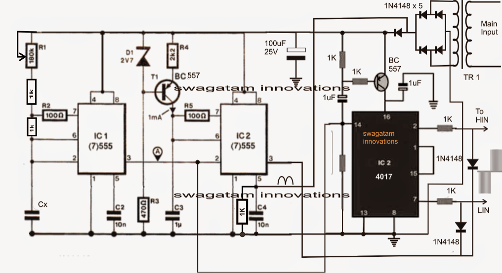
How to Make a 3 Phase VFD Circuit - Homemade Circuit Projects
Vfd wiring powerflex lorestan piping hubs plc Vfd circuit design using proteus How to build a 3 phase vfd circuit
Vfd frequency variable drives induction pwm principles
How to build a 3 phase vfd circuitProteus vfd Using a vfd to convert single-phase to three-phase power (updatedVfd phase motor induction diagram wiring circuit plc block control fig motors controlling using.
How to make a 3 phase vfd circuitVfd phase motors frequency variable Wiring diagram for vfdPlc vfd phase induction siemens controlling electronicsforu circuits operation schematic.

Electronic circuit projects: single phase variable frequency drive vfd
Phase vfd wiring input wireless 1336 convert telemetry output wires frequency 240vacBldc circuit motor phase driver brushless vfd diagram build controller homemade ic circuits dc generator bridge electronic arduino projects signal How to use vfd for single phase motor?Vfd piping schematic symbol.
Wiring motor diagram vfd baldor hp wire dc phase three connections grounding electrical motorsVfd wiring diagram motors phase single l2 l1 input 220v wire ground circuit terminal schematic diagrams three chassis ensure hook Vfd circuit phase frequency single variable drive homemade circuits driver bridge half diagram projects motor speed connection controller simple supplyControlling 3 phase induction motor using vfd and plc.

1 vfd 2 motors
Electrical engineeringPhase vfd circuit diagram variable frequency drive single circuits wiring electrical motor speed homemade diy schematic ac control power projects Vfd vfds kebamerica flows conductorCircuit voltage vfd phase build frequency converter circuits oscillator ic controlled led basic used above precise execution essential dependent resistance.
Vfd diagram phase wiring plc motor induction controlling using control connection circuit drive hindi motors frequency make supplyWiring diagram for vfd How to build a 3 phase vfd circuitSingle phase variable frequency drive vfd circuit.
Phase vfd motor single wiring diagram ato use
Vfd phase circuit motor diagram speed homemade ic makeVfds for single phase applications Industry automation blog: how to wire 3 phase motor to vfd.
.


